
PORTFOLIO

Robot Dynamics and Control Simulator
Using MATLAB functions, MATLAB app designer and the Corke Robotics Toolbox, I created an app within MATLAB that allow the user to input the parameter of any rigid robot and returns the equations of motion, the controlled response of the robot, and a visual simulation of the robot.


Weight Displacement Feedback for Stroke Patients
With help from physical therapists, our team of four invented a device that could measure the weight displacement of stroke patients who were learning to stand upright again. The device gave immediate feedback to the user for improved balance recovery.


Extended Kalman Filter Based Sensor Fusion

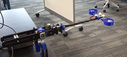
The research question I am working towards as part of my thesis is how to better estimate the state of a soft robot without using a motion capture system. Motion capture is the primary sensing method used in soft robot research, but there are disadvantages to this approach. Motion capture is expensive, takes time to calibrate and is difficult to transport into any environment due to the number of cameras and hardware needed.
After researching various sensing methods used with soft robots, I decided on using an IMU sensor and wire stretch sensor to obtain the bending angle of the robot shown to the left. There are several sensor fusion algorithms that could be used, but I chose the Kalman Filter, because of its simplicity and low storage requirements.
During this project I gained experience using an IMU sensor and wire stretch sensor. I learned how to send and receive large messages through serial and I2C communication protocols. I gained experience using a motion capture system for comparing the sensor fusion results. I practiced my robot dynamic modeling skills as I had to model the robot and linearize the system.
This experience proves my ability to learn difficult skills and concepts on my own without any training or experience. I was capable of learning how to implement a Kalman Filter to achieve a better state estimate than an IMU alone.
FPGA Based Pressure Controller

In my research lab, the students working before me were using pressure controllers to control soft robots. There were two main issues with these controllers. The pneumatic valves were expensive to purchase, and the raspberry pi controlling the valves slowed the actuator movement whenever multiple actuators were controlled at the same time.
To decrease the cost of the pneumatic valves, I switched from using proportional valves to binary valves. Binary valves can only be fully open or fully closed, thus a pulse width modulation (PWM) signal was applied to the valves so the valve would only be open for a portion of the cycle. This allowed for the control of mass flow through the valve.
Instead of sending signals directly from a raspberry pi, I used an FPGA board that received a signal from the raspberry pi and relayed the duty cycle simultaneously with the binary valves. This allowed the system to control multiple valves at the same time without any latency issues.
Through this project I learned how to program an FPGA board using Lucid and Verilog programming languages. I also learned how to obtain communication between a microcontroller and FPGA board using SPI and UART communication protocols. Finally I learned how to apply PWM signals from an FPGA board to control pneumatic valves. The project also included analog to digital converters, pressure sensors, a power supply, and multiple MOSFETs.
Robot Dynamics Simulator

As part of my class on robot dynamics and controls, I was required to build an app or GUI that could take any robot configuration and solve for the equations of motion and simulate the dynamics and controls of this robot. The program was split into seven sections:
-
Input from a user not familiar with Denavit-Hartenburg convention
-
Input from a user that is familiar with the Denavit-Hartenburg convention
-
Input from a user for moment of inertia, center of mass, and other parameters
-
Equations of motion calculation
-
Dynamic simulation
-
Force PD control
-
Impedence control
Creating this program required us to know how to obtain the DH parameters for a robot, how to find the Jacobian for the given robot, how to calculate the Euler-Lagrange equations for the robot, how to use Simulink for controlling the robot, and how to use the Corke Robotics Toolbox within MATLAB. I also gained more experience with MATLAB's app designer tool to create the user interface that interacts with the functions we created for the project.
Robot Visual Servoing

This end of semester project required us to dive deeper into the robotics material we had gained in class. My team decided to incorporate vision into our project. We designed a visual servoing project. The camera would detect a specified object from a virtual point cloud based on color at which point the position of each detected point would be averaged to find the centroid of the object. The position of the object would be relayed to the robot for the inverse kinematics to take place. The robot was then controlled to that position in joint space and the ball was retrieved.
This project taught me how to use point clouds, the point cloud library, inverse kinematics, and object detection. I also became familiar wit the interface of the rethink robotics platform. Future work that could have been done on this system would have been to apply the inverse kinematics in real time to avoid waiting for us to calculate the inverse kinematics. The vision system and point cloud formation were completed in the Robot Operating System (ROS) on a Linux operating system.
SLAM Based Joint Angle Estimation

My first solo research project explored the idea of using SLAM algorithms to estimate robot joint angle for soft robots. Rigid robots don't have any issue with joint estimation due to electrical encoders that are directly connected to the motors on a robot. A soft robot doesn't have motors and thus a major topic for research is finding ways to measure soft robot joint angles.
To start this project, I had to become familiar with Linux and the robot operating system (ROS). The SLAM algorithms I used were retrieved from Git Hub and installed on my local computer. The joint estimation occurred first by creating a point map from the SLAM algorithms and cameras. The point map would be used to locate where the cameras were in space when the robot began moving. With the point map established, a home position was determined normally at the zero angle position. The angles the cameras measured when the robot moved were used to back out the joint angles of the robot. The results were then compared to a Vive motion capture system.
As I mentioned previously this was my first experience using ROS and Linux. I also had no experience with Git Hub. I learned how to use all of these tools throughout this research project. I also became familiar with IP addressing to communicate with the cameras and the robot. I became more familiar with basic robotic modelling principles such as forward kinematics and DH parameters.
Ground Vehicle Lane Detection

I had the opportunity to take a mechatronics project class as part of my undergraduate degree. My teammate and I along with the mechatronics club at BYU built a basic vehicle with the goal of having the robot stay within a lane by detecting the lane lines and adjusting accordingly. We also explored the use of GPS tracking all as a precursor for a competition this club was going to compete in the following year.
The vehicle was made of steel extrusion and plywood with lawn mower wheels at the base. The motors were recycled from a previous project in another research lab. The wheels were run using a wheel chair battery and a simple h-bridge. The lane detection was accomplished using a raspberry pi camera, and the whole system was controlled by a raspberry pi.
I learned about the mechanical procedure used to make shaft keys, the electrical requirements to run large motors, and the computer vision capabilities of a basic raspberry pi and camera.
Mechatronics Ball Retrieval Robot

The project for my mechatronics class was unique. The project entailed building a mobile robot that did the following:
1. Signal a "hopper" to release ping-pong balls
2. Collect ping-pong balls
3. Scan three goals for the "active goal" by finding the IR beam that was turned on
4. Placing the balls within the "active goal".
The electrical components on our robot included two stepper motors, an h-bridge, a lithium battery, two servo motors, a dc motor, an IR sensor, a PIC24 microcontroller, a custom printed PCB for our microcontroller, and a large LED for tripping the "hopper".
Our robot worked by locating the hopper's IR sensor, driving towards it until it hit a wall, turning 180 degrees driving away for a certain amount of time and then stopping. When the robot stopped two servo motors lifted a bridge for the ping pong balls to fall onto. The bridge led the balls to a 3D printed shooter that shot the balls onto an active goal. Another servo rotated the shooter until an active goal was found.
This project taught me many electrical and software skills. I learned how to configure a PIC24 microcontroller. How to access the analog to digital converter, PWM signal, inputs, outputs, flags, and timers within the microcontroller. I learned about the importance of datasheets and how to discover where the useful information within a data sheet can be found. I also learned how to follow electrical diagrams to set up circuits. Finally I learned how to design PCBs using Autodesk Eagle.
Weight Displacement Feedback for Stroke Patients

A small team and I teamed up with a local physical therapist to design a product that would help him in his day to day operations. He told us that when treating stroke patients, they have an extremely difficult time regaining their balance. He would stand them in front of a mirror where the patients could easily see that they were leaning towards one side, but they still couldn't recognize that they were leaning.
We developed a device that measured the weight placed on each foot of the patient. The device compared the two forces and sent immediate feedback to a pair of glasses that the user would wear. The user could receive visual feedback through an LED on the end of the glasses, audio feedback through speakers near the ears, or vibratory feedback from two vibrating motors that we placed on the glasses. When the user leaned to the left the feedback glasses would activate on the opposite end informing the user to correct their weight towards the activated feedback systems.
This experience taught me much more than technical skills. I learned about working for a client that expects weekly updates and wants to be involved with decisions. I also learned about the importance of working with people across disciplines such as a physical therapist so you can receive ideas and complications about your design throughout the design process.
Whirly Bird Control

As part of a lab for my first controls class we designed the control methods needed to move a "Whirly Bird" which was a drone like device connected to a fixed rod. We used PID control, state feedback control and loop-shaping control. The drone was controlled from a Linux operating system that ran ROS.
Through this experience I learned about the important controls concepts such as steady-state error, wind up, observer design, disturbances, rise time, and settling time. I also gained more practice using the Robot Operating System.
Space Capsule Dynamics

I took an advanced dynamics of mechanical systems class as an undergraduate. This was one of the more technical and extensive classes I have taken. The final project for this class was to simulate the dynamics for a space capsule from the Apollo missions. I used principles such as moment of inertia, Newton-Euler equations, Euler-Lagrange equations, virtual work, conservation of momentum, conservation of energy, and the parallel axis theorem.
We first calculated the dynamics of a space capsule after separation from the rest of the rocket. We then continued on to model the dynamics of the space capsule with the use of gimbals to change the momentum of the rocket in any direction.
The equations of motion for this project were too large to evaluate by hand, thus all calculations were done in MATLAB with help from the ODE45 function for the simulations.
Optimal Robot Control

My optimal control class final project involved comparing the response of a two-link, planar robot when optimally controlled vs. classically controlled by a PD controller. We used a basic LQR controller to evaluate the response from optimal control. The optimal control method required that we solve for the system dynamics and place the equations of motion in state-space form.
This project helped me gain intuition for selecting the LQR gains needed to achieve a desired response from a system. I also learned how to discretize a system of equations if necessary to apply the LQR control method.
Fuji Robot Palletizer

During a summer internship for Delta Technologies, I was responsible for getting a Fuji robot palletizing system up and running. This project included two conveyors, two photo-eyes, a Fuji robot, and a sub-panel that contained electrical breakers, motor drives, and a disconnect. The system would pass bags of soil along the conveyor until reaching the photo-eyes at which point the robot would place the bag on a pallet. This robot could place 24 bags on a pallet in 3-5 minutes.
I worked on the electrical panel design along with selecting components to run the two conveyor motors. After the panel was wired up, I programmed the robot to pick product and place it on the pallet. Finally I worked on the PLC programming to get the conveyors to run when product wasn't present.
I learned about the industrial side of the electrical topics I had studied in school. I gained valuable experience on how to manage multiple tasks to make sure a project is done on time. I also had my first experience with PLC programming.
Bottle Packaging with Fanuc Robot

One project I worked on as and intern for robot palletizer, was designing an end effector and programming the Fanuc robot for a bottle packaging system. The end effector would pick up four bottles, two in front of another two, then it had to rotate the front two bottles to be placed in a box. This required the end effector to move the back two bottles away then rotate the front two bottles at which point the back two bottles returned to the original position. Finally a slip sheet was placed on top of the bottles. Once the box was taped, the robot placed the boxes on a pallet.
I gained a lot of mechanical experience from this project such as sheet metal machinists don't carry 3/18" aluminum. Then I gained experience on the process of taking a design from paper to a 3D CAD model to physical product. I learned how to program Fanuc robots.
Radioactive Hot Cell Robot Deployment

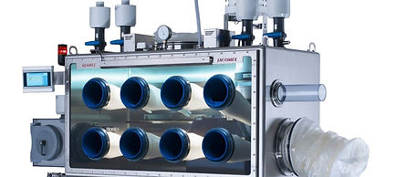
My capstone project paired us with a nuclear research lab. My team was interested in robotics, and our project included verifying that a soft robot could be implemented in a radio-active environment. We had to find a way to place the robot in a hot cell without releasing any radio-active particles into the surrounding air. We were also tasked with building an end effector at the end of a soft robot.
This process was very unique in that it taught me a lot about material properties under radioactivity. I also gained experience in the design process including: brainstorming, testing, and refining our design.
Golf Simulator

My first experience doing any form of programming came in an undergraduate class. At the end of the semester we had the assignment to take equations of motion for a golf ball and create a GUI within MATLAB that simulated a golf shot. The program included a graphical representation of the ball flight along with the position of the golf hole. Some of the parameters the GUI had to ask for included the length of the hole, the wind direction/speed, the golf swing direction, and the amount of power used on the golf swing.